Blog Barista: Greg Antrim | Aug 15, 2018 | Internet of Things | Brew time: 10 min
The internet of things (IoT) has exploded in recent years. Lights, cars, thermostats, even plants are now connected devices. Devices like the Amazon Echo and Google Home have made things even more convenient by adding voice commands to the mix.
One of the most popular platforms for IoT is the Arduino. Used by novices and experts alike, an Arduino can handle almost limitless tasks. When it comes to connecting your Arduino to the internet there are many options, but one of the most popular and widely available is the ESP8266.
Getting an ESP8266 module working and communicating with your Arduino, however, can be a complicated process. I recently went through the process myself and was shocked at how few good and complete guides there were out there. Luckily for you, I’m about to fix that situation. I have poured through forum posts, blogs with incomplete information, and half-working code samples so you don’t have to.
This post will give you everything you need to get your ESP8266 module connected and accepting commands. Specifically, we will be covering:
- Materials and software needed
- Wiring your ESP8266 module to your Arduino for testing and programming
- Initial programming of the ESP8266 including changing the mode, baud rate, and verifying that you can connect to your router
- Wiring your ESP8266 module to your Arduino for real world use
- Code needed to accept and handle JSON data
- Sending JSON Requests to the ESP Module and monitoring the output
Materials and Software
First, I would like to clarify that this post pertains specifically to a standalone ESP8266 module (Image below). There are several boards out there that have the ESP8266 chip built into the board, and the process for such boards may be different.
Hardware:
- Arduino Uno
- Standalone ESP8266 Module
- Jumper Wires
- Breadboard
- USB 2.0 Type A Male to Type B Male Cable
Software:
- Arduino IDE
- PlatformIO IDE via Visual Studio Code
- REST Client
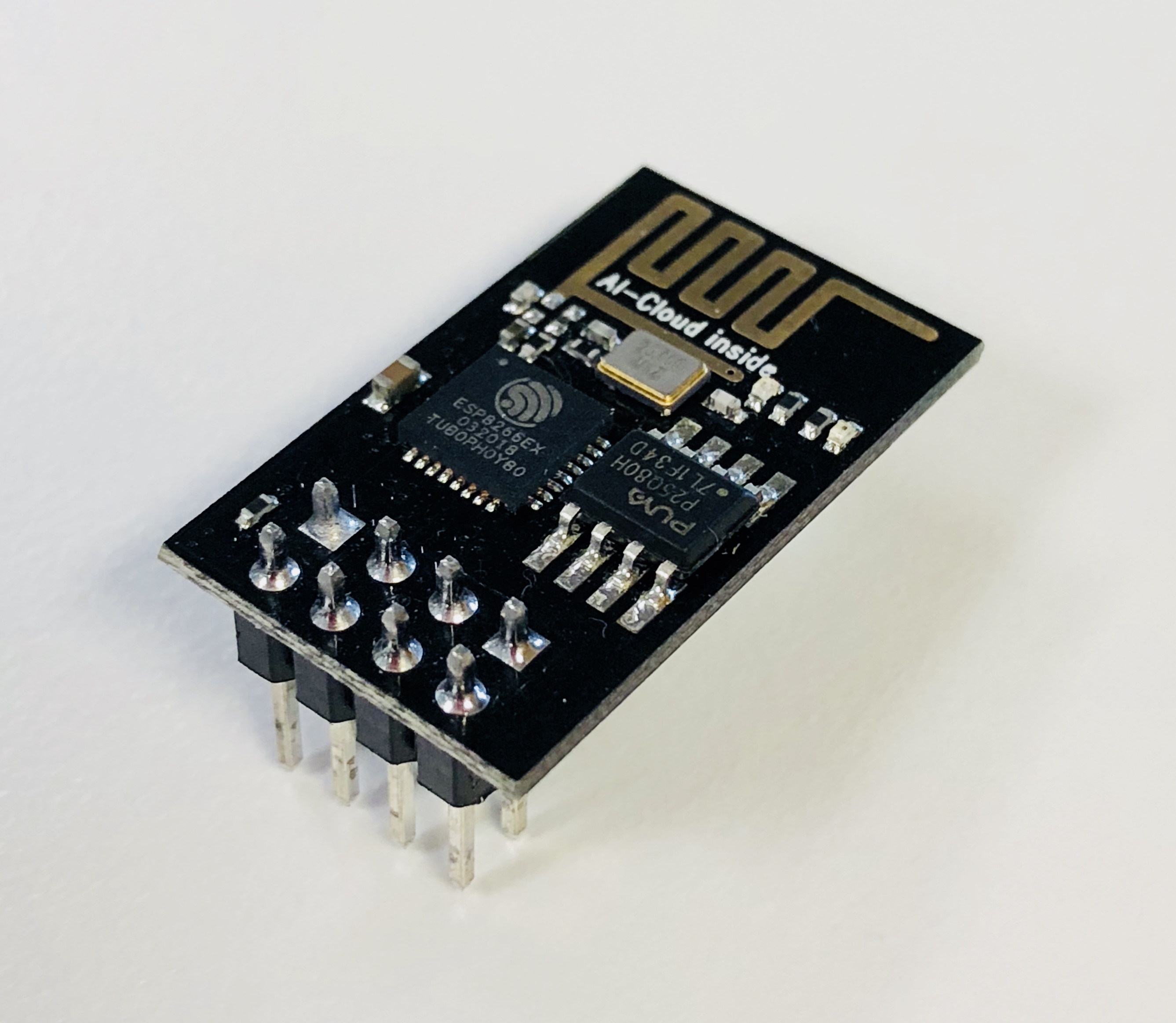
Above image: A Makerfocus ESP8266 wireless wifi transceiver module.
The code provided should also work in the standard Arduino IDE, but for the actual coding portion of this guide, I’d recommend PlatformIO via VS Code since it has better built in formatting, it’s easier to add packages, and most importantly, it has a dark theme. As far as a REST Client goes, I’ve been using Insomnia, but other clients such as Postman will work just as well.
Wiring ESP8266 To Arduino for Programming
Before wiring, I recommend that you connect your Arduino to your computer and flash the “Bare Minimum” example sketch to the board. This will ensure that nothing else is running on your Arduino.
We will first be connecting the ESP8266 to our Arduino to do some initial setup. I found the wiring configuration thanks to a helpful post on the Arduino forums, though I did have to make some modifications.
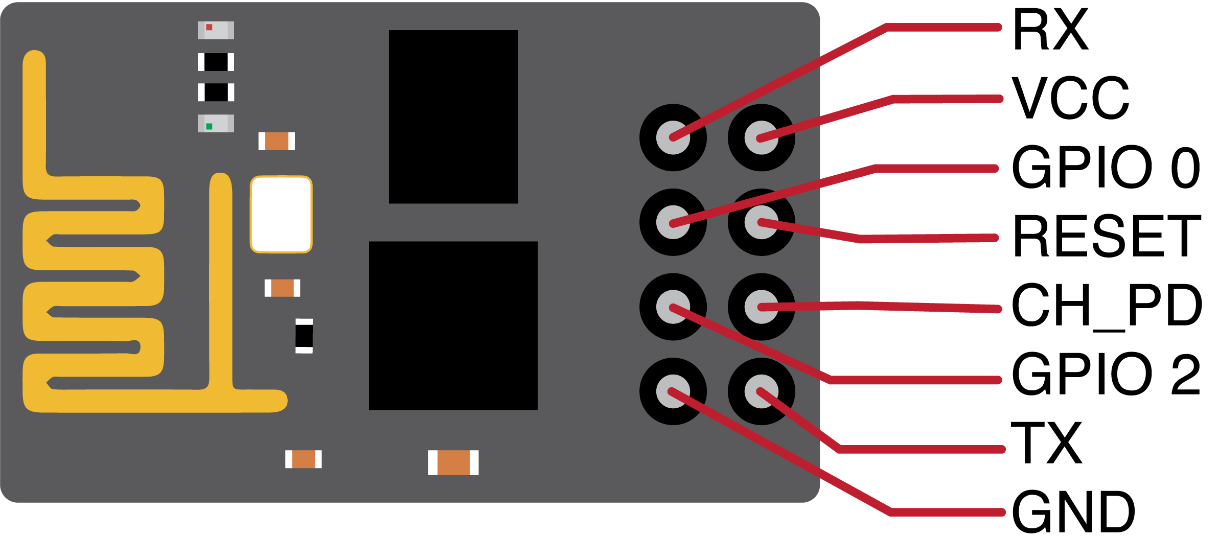
The wiring configuration for sending commands to the ESP8266 is different than the wiring configuration for using the ESP8266 so make sure to follow along closely. See the image below for the ESP8266 Pinout.
Connect the ESP8266 to your Arduino Uno as follows.
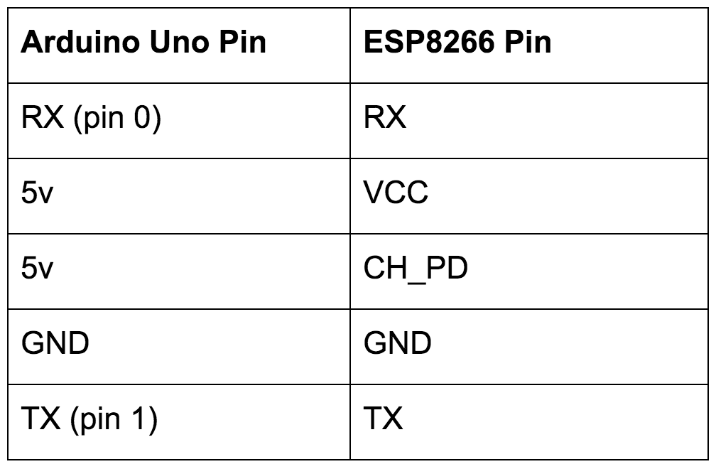
Note that while the ESP8266 is rated at 3.3v, we are connecting it to the 5v line from the Arduino. This is because the 3.3v line from the Arduino does not reliably provide enough power.
I have been running the module at 5v for months now and haven’t had any issues. If you are really worried about it, you can purchase a voltage regulator that will put out a reliable 3.3v.
Initial Programming of ESP8266
In order to get our ESP8266 to work properly with our Arduino, we need to do some initial programming. Specifically, we will be changing the ESP8266 to work as an access point and a client and changing the baud rate. Since most code samples out there are communicating with the ESP module with a baud rate of 9600, that’s what we will use. We will also verify that the ESP8266 module can connect to our router.
With your Arduino Uno connected to your computer, open the serial monitor via the Arduino IDE (ctrl + shift + m). On the bottom of the serial monitor there are dropdowns for line endings and baud rate. Set line endings to “Both NL & CR” and change the baud rate to “115200”. Then send the following commands:
1. Verify that the ESP8266 is connected properly.
Command to send: AT
Expected response: OK
2. Change the mode.
Command to send: AT+CWMODE=3
Expected response: OK
3. Connect to your router (Make sure to replace YOUR_SSID and YOUR_WIFI_PASSWORD).
Command to send: AT+CWJAP=”YOUR_SSID”,”YOUR_WIFI_PASSWORD”
Expected response:
WIFI CONNECTED
WIFI GOT IP
OK
4. Set baud rate to 9600.
Command to send: AT+UART=9600,8,1,0,0
Expected response: OK
5. Verify that the ESP8266 is communicating with baud rate of 9600.
Command to send: AT
Expected response: OK
If you are curious about what each command does, or are looking for more info about the commands that are available, I found this page both readable and incredibly helpful.
Wiring the ESP8266 for Real World Use
Now that we have set up our ESP module and verified that it can connect to our wireless network, it’s time to connect the ESP module to the Arduino for actual use.
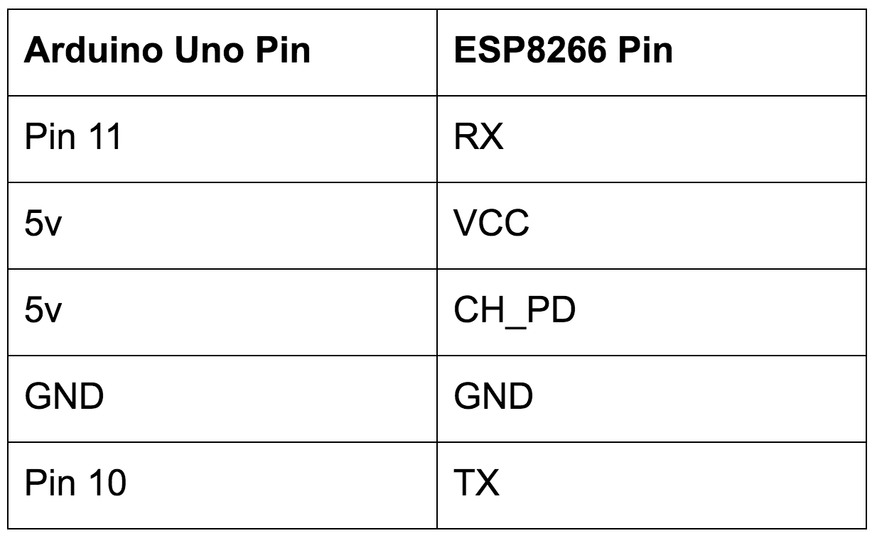
In order to communicate with the ESP Module, we need to connect the TX and RX Lines to Digital Pins. You may use any two pins from 8-13, but for this tutorial I will be using pin 11 for RX and pin 10 for TX.
For reference, here is how everything should be connected:
Sending JSON Data to the ESP8266
Now that we have everything wired its time to start sending commands to our ESP module. In order to keep things simple, I am only including the code to initialize the ESP server and parse the JSON. What you do once you have the JSON data is up to you. I personally use it to control my lights with one JSON payload turning the lights off and another turning the lights on.
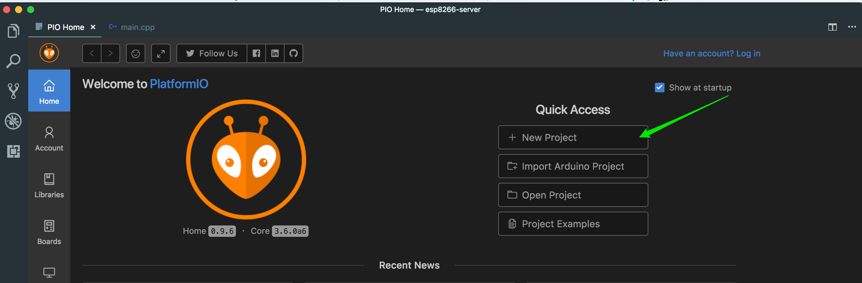
To get started, open Visual studio code. If you have the PlatformIO IDE set up correctly, a tab should open titled “PIO HOME”. From there follow these steps:
1. Under the Quick Access menu, click New project
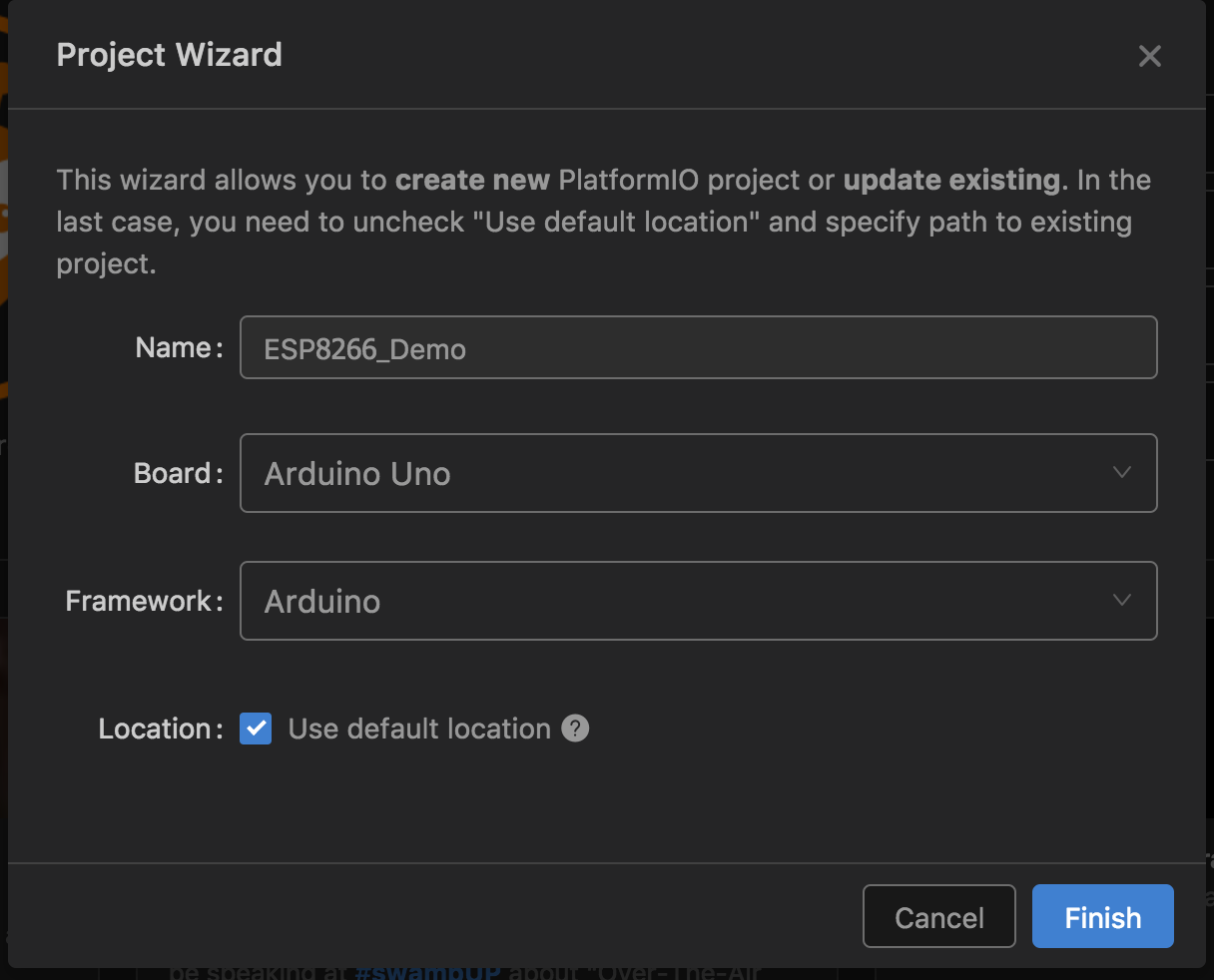
2. On the Project Wizard dialog:
a. Enter a project name in the Name field
b. Select Arduino Uno from the Board dropdown
c. Click Finish
3. Go back to the PIO Home tab and select Libraries from the side navigation bar
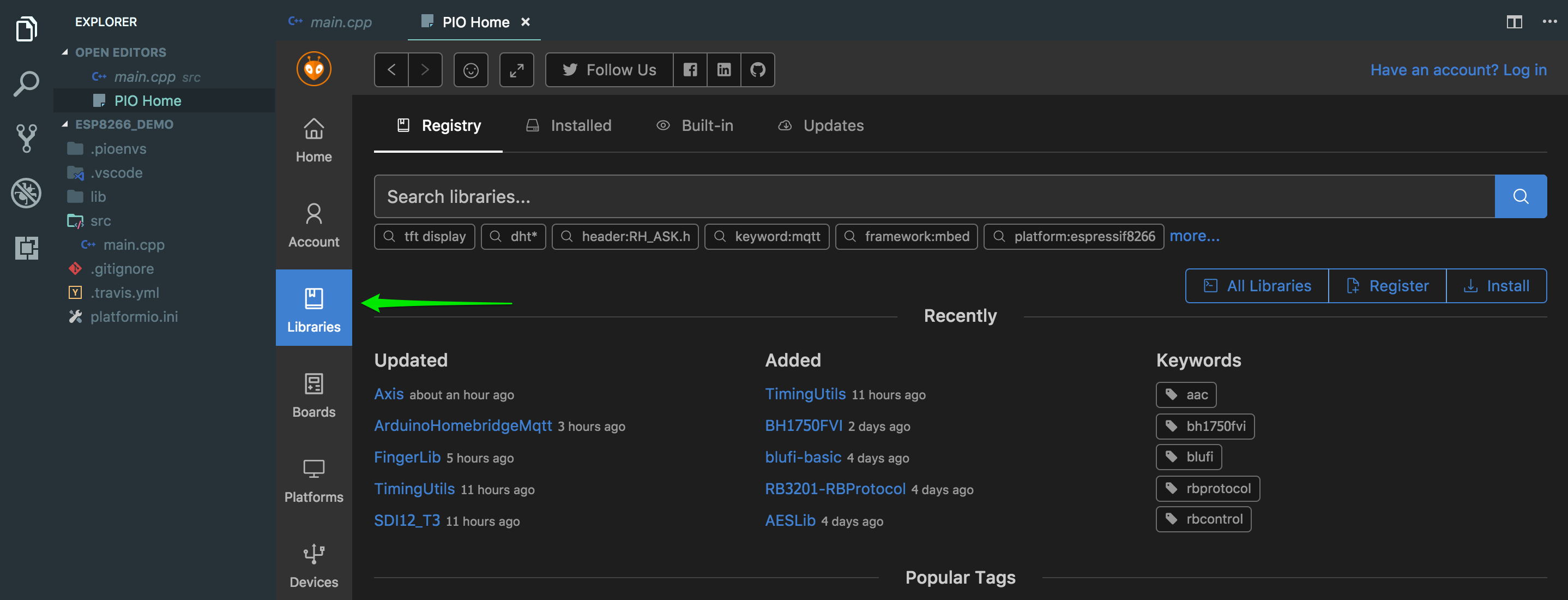
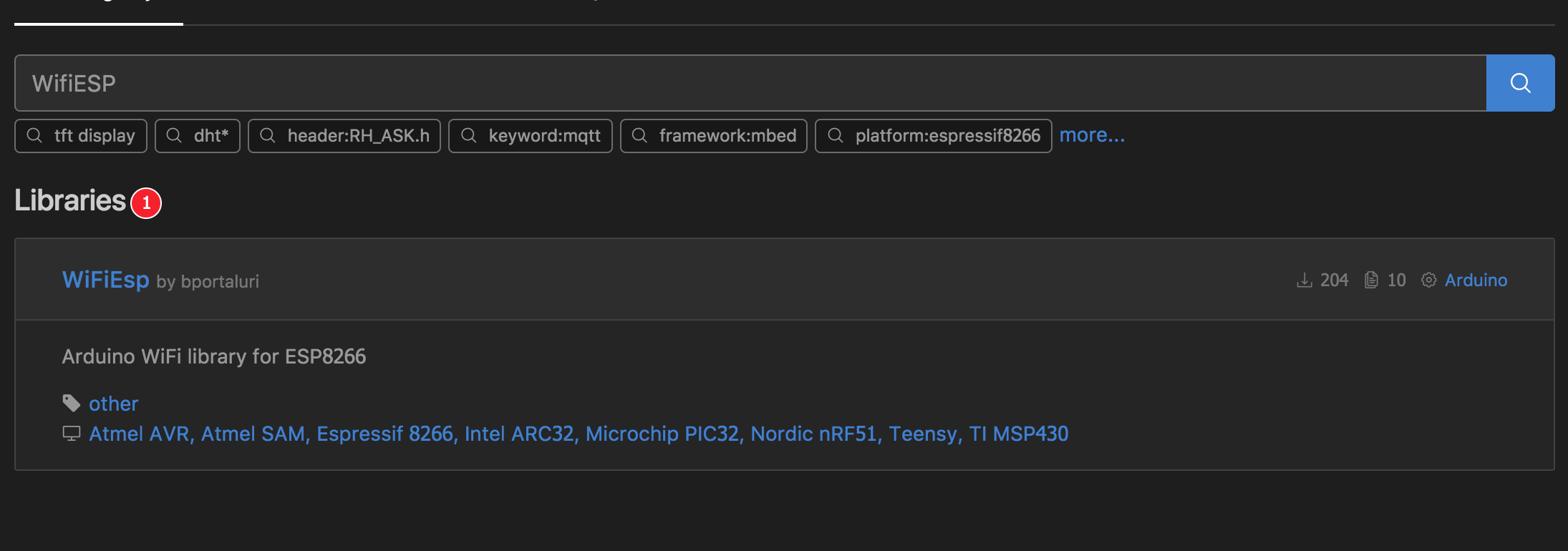
4. In the search box, type WifiESP and hit Enter
5. Install the library by bportaluri
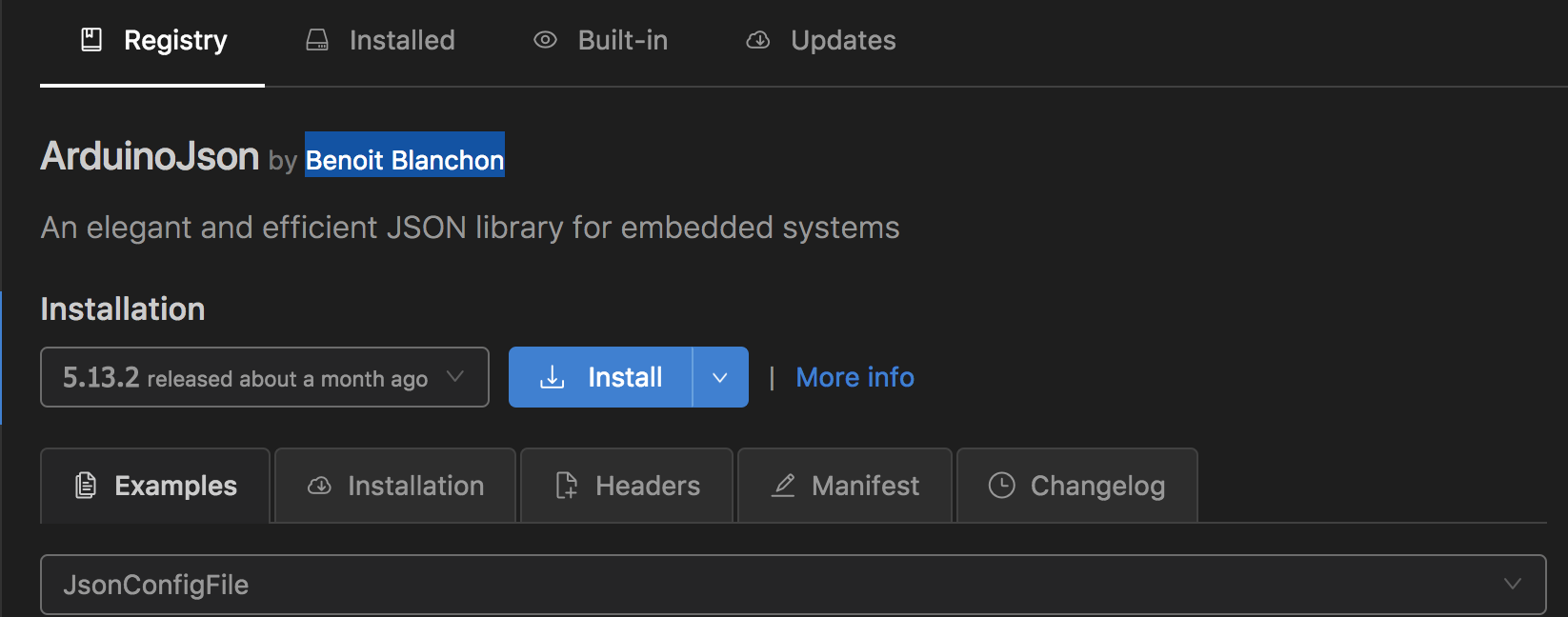
6. Clear the Search box and type in ArduinoJson
7. Install the library by Benoit Blanchon
8. From the file explorer on the left side, open src/main.cpp
9. Copy and paste the code below:
Make sure to change line 11 to match the pins that you used (if you used 10 and 11 as recommended, no modification is needed). Also, be sure to enter your SSID and WIFI password on lines 18 and 19.
Before we upload the code to the Arduino, let’s take a look at what is happening. Here is a quick overview:
Setup function
- Initialize the ESP module via the WifiESP Library we installed earlier
- Connect to our wireless network and wait for that connection to be established
- Print out our local IP so that we can use it later in our REST requests
- Start our server and tell it to listen for clients on port 80, the standard HTTP port
Loop function
We continuously wait for a client to connect. Once a client is connected:
- Print that a client has connected
- Parse the incoming request
- Search the request for the opening JSON bracket
- Read in request until closing JSON bracket is found
- Add brackets back around the JSON data
- Use the ArduinoJSON library to convert our JSON string into a JSON object
- NOTE: If you change the JSON request format at all, you will need to re-calculate your buffer size using this tool
- Get and print the value of the “action” key in our JSON object.
- Print a different message based on what the value of the action key was
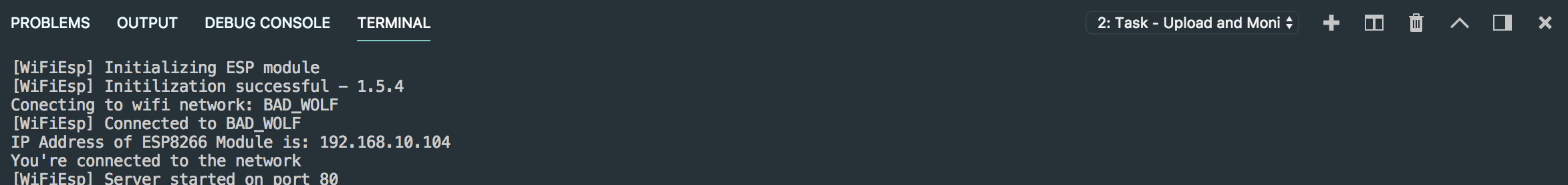
Now it’s time to upload everything to the board.
From Visual Studio Code, open the Tasks menu and select Run Task, then select PlatformIO: Upload and monitor.
If everything goes right, you should see the following in the console:
Sending JSON Request to ESP8266
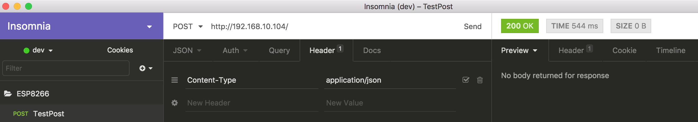
All that’s left to do now is send a request to our module and verify that the request is received. Make sure you grabbed the IP address from the last step and that your upload and monitor task is still running. Then, open up your favorite REST client and enter the following:
URL: http://YOUR_ESP_IP_ADDRESS_HERE/
Headers:
Content-Type: application/JSON
Request Body:
{
“action”: “off”
}
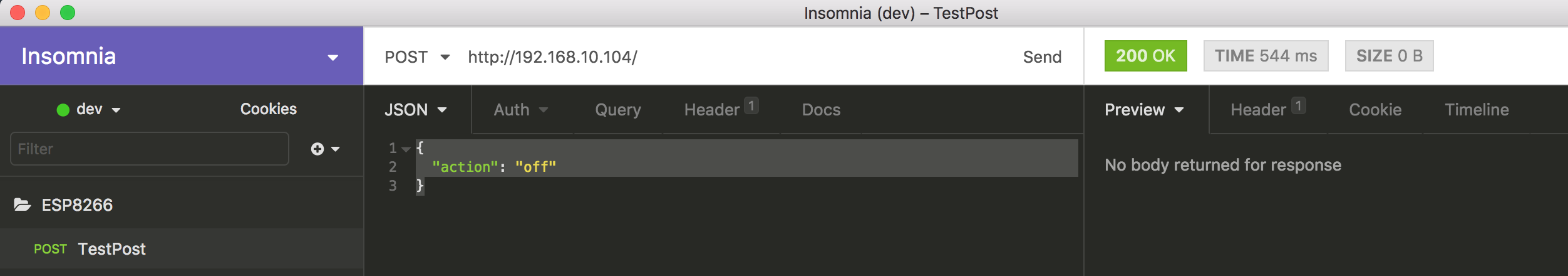
Send the request and go back to Visual studio code. You should now see the following in the upload and monitor console:
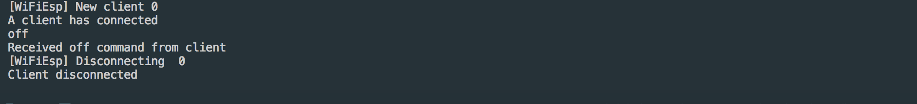
That’s it!
You now have an Arduino capable of receiving commands via WIFI. All you should need to do now is decide what your JSON data looks like and what actions need to be taken once that data is received.
Hopefully you found this blog post helpful and I’ve spared you the pain of tracking down all of this information yourself. Let me know what you think in the comments.
Bonus points for links to projects that made use of this guide.
18 Comments
Other recent posts:

Kunz, Leigh and Associates (KL&A) Announces the Retirement of KL&A Co-Founder John Leigh
OKEMOS, MI, April 11, 2023 – Kunz, Leigh and Associates (KL&A) announces the recent retirement of KL&A Co-Founder John Leigh as of March 31, 2023. Mr. Leigh began his career as a developer working on large mainframe systems before moving…

Team Building in a Remote Environment
Blog Barista: Dana Graham | June 15th, 2022 | Culture | Brew time: 5 min
Let me start by saying I don’t care for the term “work family.” I have a family I love, and they have absolutely nothing to do with my career. I want my work life to be its own entity. I like boundaries (and the George Costanza Worlds Theory). Certainly, I want to enjoy and trust my coworkers, and I want to feel supported and cared for…
Would that be possible to create a case where Arduino is our main chip and ESP is used just to send and receive data based on requests to an API?
Hey Paul,
Thanks for the comment! I’m not sure what your specific project needs are but this tutorial uses the Arduino as the main board, the ESP is used to connect to a Wi-Fi network and receive API requests. Making API requests should also be possible as long as the Wi-Fi network you are connected to is also connected to the internet. If you wanted to provide more details on what you were trying to accomplish I would be glad to point you in the right direction.
everything works fine but at the end i get this error
[WiFiEsp] Initializing ESP module
[WiFiEsp] >>> TIMEOUT >>>
[WiFiEsp] Warning: Unsupported firmware
Conecting to wifi network: GetYourOwnWifi
[WiFiEsp] Failed connecting to GetYourOwnWifi
Hey Anas,
The timeout unfortunately isn’t the most descriptive error but there are a couple things you can check.
1. Verify that VCC and CH_PD are connected to the 5v pin on the Arduino or to a regulated 3.3v power source. As mentioned in the article the 3.3v pin on the Arduino doesn’t actually supply a reliable 3.3v.
2. Try swapping the TX and RX wires. It’s possible that you just have them backwards (I usually get them wrong the first time)
3. Try connecting to your Wi-Fi network directly from the serial monitor to eliminate any code issues. (See Initial Programming Step 3)
4. Verify that you have the correct firmware version. The WiFiEsp library supports ESP SDK 1.1.1 (AT version 0.25) and above. You can check your firmware version by sending the command “AT+GMR” through the serial monitor. You can see this post for instructions on how to upgrade: https://github.com/bportaluri/WiFiEsp/issues/48.
Note that to send AT commands you will need to connect the ESP8266 to the Arduino as described in the “Wiring ESP8266 To Arduino for Programming”.
If that doesn’t work let me know and we can continue troubleshooting.
I have the version
“AT+GMR =
0018000902-AI03
How do I update it?
I looked in link but I didn’t understand
shouldn’t it RX and TX of Arduino are connected to TX and RX of esp8266?
Hey KKL,
Thanks for taking the time to read and respond. I’m not sure which step you are referring to, so I’ll comment on both.
In the “Wiring ESP8266 To Arduino for Programming” step, you want to connect ESP8266 RX to Arduino RX and ESP8266 TX to Arduino TX. I know that seems wrong, but you will not be able to send AT commands to the chip if you connect ESP8266 RX to Arduino TX and ESP8266 TX to Arduino RX .
In the “Wiring the ESP8266 for Real World Use” step need to connect ESP8266 RX to pin 11 and ESP8266 TX to pin 10 in order for the provided code to work. Technically any digital pin will work for communication between the Arduino and the ESP8266 as long as you modify line 11: SoftwareSerial Serial1(10, 11); accordingly. The RX and TX pins on the Arduino are technically digital pins 0 and 1 so they could be used as well, however it should be noted that those pins are also used for USB communication and for standard serial communication so if you use those pins you won’t be able to upload sketches or use Serial anywhere in your code. Additionally, most of the ESP8266 code samples out there use digital pins 8-12.
Hi! Awesome Tutorial, I was able to get this up and running with little issue. I am curious how you would recommend I take the project further by submitting JSON from a webpage or something similar instead of through Insomnia. The ultimate goal would be to send it JSON from a webAPI I would like to use. Let me know your thoughts! Thanks!
Hey Matt,
Thanks for the feedback, I’m glad you were able to get things working. If you are looking to use JSON from a Web API, the first thing you would need to do is make your ESP8266 accessible from the web. There are a couple of ways to do this, and the solution you choose will depend on your needs.
The first, and probably the easiest method (assuming you have admin control of your router) is to set up port forwarding. While I have not tested it, this seems to be a good guide: https://www.instructables.com/id/Control-ESP8266-Over-the-Internet-from-Anywhere/. Note that you may need to change the port number (line 23 of my code above) to something other than 80 since 80 is the default HTTP port and may already be used. With this method, you will have to use your public IP, rather than a human readable URL to access your ESP8266. That port will also be open to all traffic which could pose security risks.
The second option is to use a separate web server as a middleman. I have a Raspberry Pi on my local network that starts Ngrok (https://ngrok.com/) on boot. I also have a small Nodejs Express app on that Raspberry Pi that listens for requests and then forwards them to the correct internal IP. While setup is obviously more complex, it has a few advantages. First, Ngrok gives you a human readable URL. This is easier to remember, and it means that you don’t have to update code and IP addresses should your external IP address change. Ngrok also allows you to use HTTP basic authentication so you can secure things with a username and password. Additionally, you can handle more advanced routing logic, such as sending multiple internal web requests via a single external URL, inside of the NodeJS Express app. Finally, with this approach, you can set up SSL via Nginx and Let’s Encrypt for some added security.
Let me know if you have any questions. I’m planning on doing a follow-up blog post on this subject within the next week or two, so if there is a specific use case you had in mind be sure to let me know.
Hello Greg! Thanks for the awesome feedback! I also thought that the best approach would be to use a webpage as a middle man of sorts. That way I can process the API JSON on that site and then only send the relevant information back to the arduino/esp8266 setup.
I would love to read a tutorial about a middle man option like you mentioned and hope that you do go ahead and make one! The issue i seem to be having is to send the data from a webpage similar to the way you used the insomnia client. I have tried JQuery code etc but no luck yet.
I am looking forward to some more blog posts in this area of knowledge. After many hours of scouring the internet your tutorial was by far the best to getting the Arduino connected to the internet via the ESP8266 module!
Thanks again,
Matt
Hey Matt, I just wanted to let you know that I finally completed my follow-up posts. Check them out here: https://kunzleigh.com/command-your-arduino-from-anywhere-part-1-port-forwarding/ and here: https://kunzleigh.com/command-your-arduino-from-anywhere-part-2-ngrok-middleman-server/
Hi, I was trying to configure my esp to act as an access point but when I give the command AW+CWJAP=”SSIDNAME”,”PASSWORD”
There is an error
+cwjap:3
FAIL
Hey Nischay,
Thanks for taking the time to read this post. The error you are getting could be due to a couple of issues so here are some things to try:
1. First, make sure that you are using the correct characters in your command. I noticed in your command that your quotation marks are ” rather than “. It’s a small difference, and easy to miss, but they are technically two different characters. This can happen when copying from the web as some sites render quotation marks differently. After you copy the command, I’ve found its best to paste it into a simple text editor like notepad and then re-type the Quotation marks yourself.
2. If possible, try connecting to a different router. Sometimes your router settings can be the issue, and testing with a different router can confirm that. I would also make sure that you don’t have any special characters in your SSID as sometimes the ESP can have trouble with that. Also, make sure that DHCP is enabled on your router.
3. Try setting your ESP to a different mode using the “AT+CWMODE=2” or “AT+CWMODE=3” commands. Sometimes just toggling from one mode to another can fix issues.
4. Make sure you are using the correct commands for your device and firmware version.
Hopefully one of those fixes your issue.
It works if you set the baud rate of the esp8266 to 9600. By default it should be 115200
Got stuck at first phase. I have connected wires as you have defined. When i sent AT command, there is no response in serial monitor.
I have exactly the same issue did you found a solution?
Best regards.
@jay i think i found the solution, just verify that there is no program running on your arduino which communicates with the esp8266.
I Just uploaded a program like:
void setup() {
// initialize digital pin LED_BUILTIN as an output.
pinMode(12, OUTPUT);
}
// the loop function runs over and over again forever
void loop() {
}
and than i was able to send commands with the serial monitor
Hi Greg, I got to make everything work in the initial programming, but when using your code for real world, I got stuck in “connecting to WIFI:” It never gets the WL_CONNECTED. I checked the value and it returns 2 as status